• paper house template (LINK FOR DOWNLOAD)
• conductive copper tape (5mm)
• LED
• glue stick
• Arduino Nano
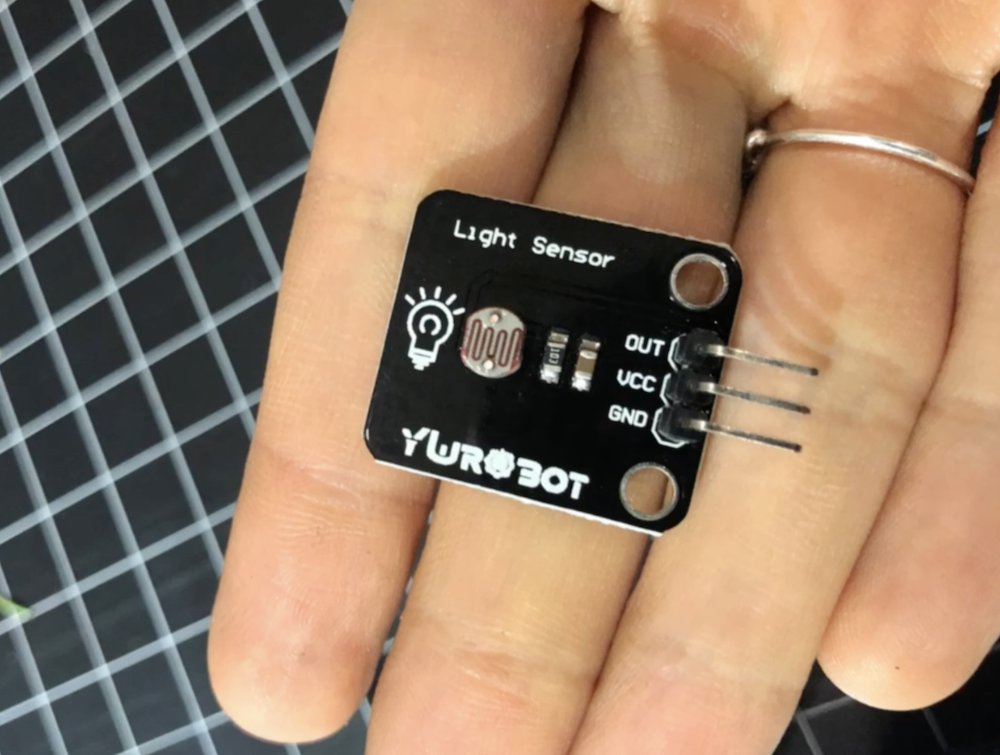
• Light sensor (I used a sensor from YUROBOT)
• male-to-female wires
• pedestal for placing the house and organizing the wires (I used a left over package from IKEA)
• decoration (I used Template Maker to generate some 3D shapes to create trees and buildings around the house
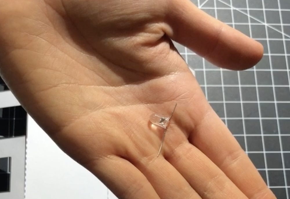
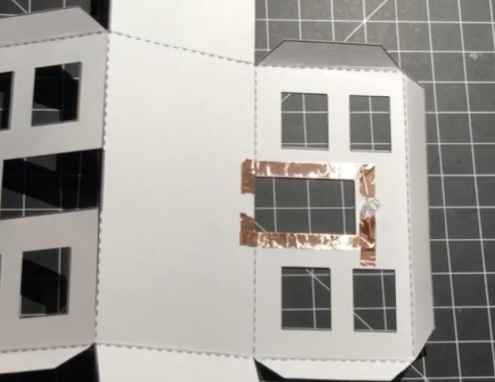
2. Once you have finished taping, attach LED to the circuit. REMEMBER, long leg goes to the positive side, or VCC/signal; short leg goes to the negative side, or GND.
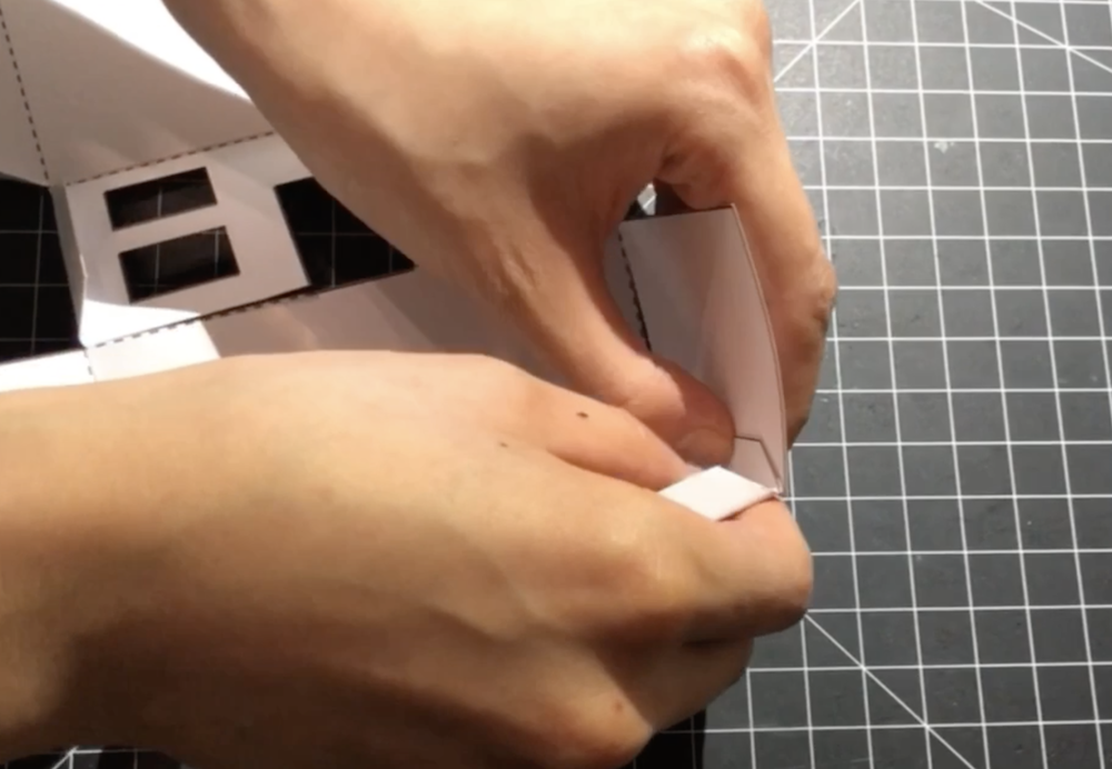
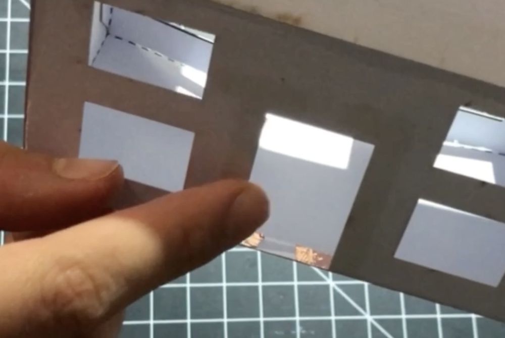
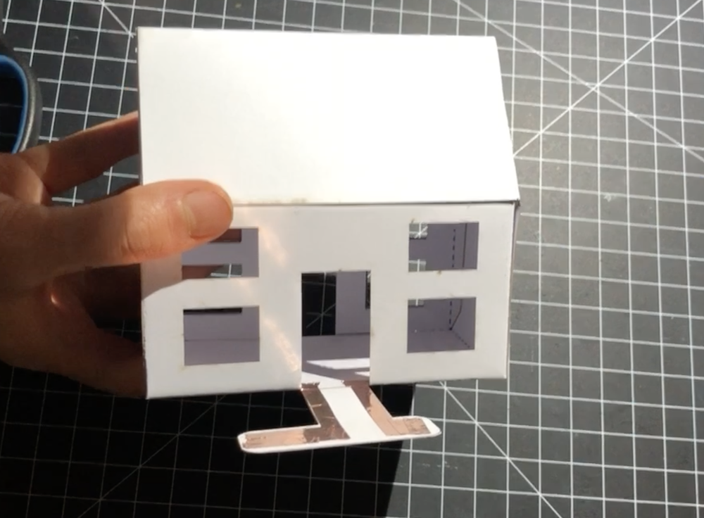
3. Fold the edges of the house along the dashed line. Then, assemble the house with a glue stick.
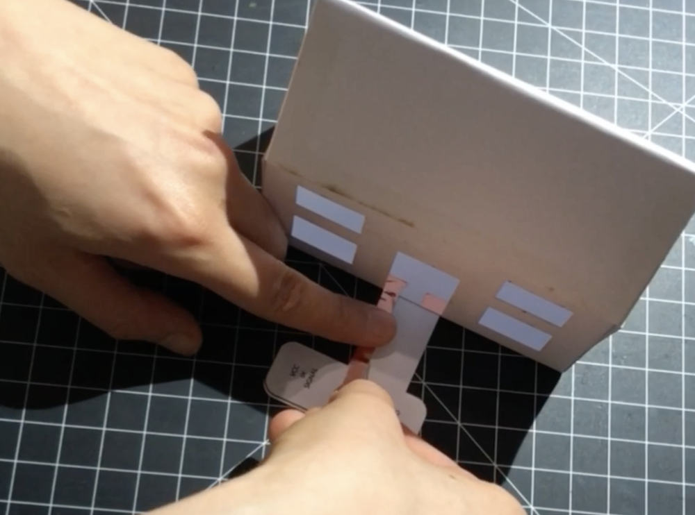
4. Build a path from the LED circuit to the Arduino Nano wiring: attach the path template to the bottom of the house, as shown in the image below.
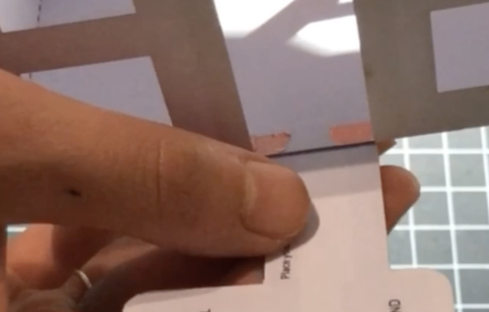
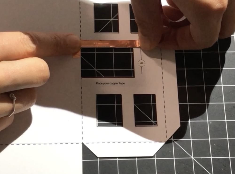
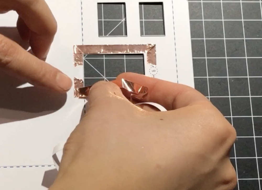
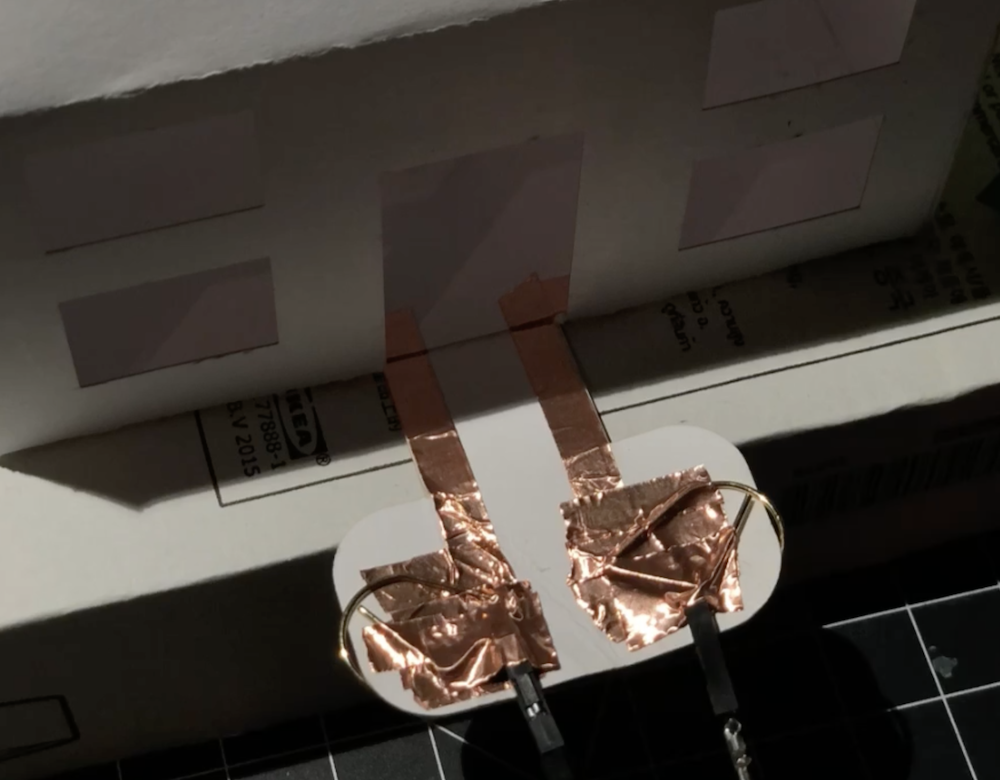
5. Attach copper tape to the path by continuing from the previous circuit.
6. Wire the LED (+ to digital pin, - to GND) and the light sensor (OUT to analog pin, + to 3V, - to GND) with male-to-female wire to Arduino Nano. For the LED wiring, I taped down the female side of the wire to the paper circuit with copper tape.
7. Program the light sensor via Arduino IDE. Here is the program I have uploaded:
    const int darkLevel = 5;
    int lightValue;
    int lightsensor=A0;
    int LED=10;

    void setup() {
    pinMode(lightsensor, INPUT);
    pinMode(LED, OUTPUT);
    Serial.begin(9600);
    }

    void loop() {
    lightValue = analogRead(lightsensor);
    Serial.println(lightValue);
    if (lightValue <= darkLevel) {
    digitalWrite (LED,HIGH);
    } else {
    digitalWrite (LED, LOW);
    }
    delay(100);
    }